ASP.NET MVC is not a new architecture pattern but the debate still goes on in
development circles as to which is better
.So, I just want to try to clear that differences and right usage of patterns.
Let we go 10-15 years back and see how web has changed..
History of the web
We've seen a number of changes in web development over the years, not always for the better:
Common Gateway Interface (CGI) - Scripting language running outside
the web server. Time and resource intensive
Microsoft Internet Database Connector (IDC) - Simple wrapper for SQL
queries, with templates to format the results
Active Server Pages (ASP) - Big step forward but mixture of HTML and
code became cumbersome and confusing. Known as "spaghetti code"
ASP.NET Web Forms - Compiled web "applications" which hides the
"statelessness" of HTTP. Allowed Windows developers to more easily
transfer to web developers. Heavy on bandwidth. Untestable.
ASP.NET MVC - Reworking of Xerox Smalltalk paradigm from the 1970's.
Works WITH statelessness nature of HTTP rather than hiding it. Removes
ViewState
Looking Back
We've seen a number
of changes in web development over the years, like: Common Gateway Interface
(CGI) - Scripting language running outside the web server. Time and resource
intensive Microsoft Internet Database Connector (IDC) - Simple wrapper for SQL
queries, with templates to format the results Scripting Active Server Pages
(ASP) - Big step forward but mixture of HTML and code became bit confusing.
Known as ASP.NET Web Forms - Compiled web "applications". It seems to take this
bit confusion away We are thinking MVC :)
Choosing Between ASP.NET Web Forms and ASP.NET MVC?
Fact is that both
are just ASP.NET server side technologies known as Active Server Pages .Now
where we split them or where is difference ? Actually these are architectural
patterns or the way we develop .net web based applications.Both can be the “best
choice” for a specific solution depending application development
requirements . When facing a decision to choose between ASP.NET Web Forms
or ASP.NET MVC it is important to know that neither technology is meant to
replace the other. Both are running parallely and are used as per project
requirement.Now, gap between two is getting filled as Microsoft is parellely including best features of MVC into ASP.NET Webform pattern also.
Some important
factors we should consider while making the choice is
If we really
need to develop application rapidly, i believe ASP.NET Web Forms pattern is
only and best choice
Unit Testing -
If TDD test driven development is not important, ASP.NET web form is best
choice.
If Application
really doesn't bother about UI scalability(UI for multiple devices) .
ASP.NET is again best choice
Apart, there are
lots of questions we need to consider before choosing architectural pattern like
Do we have
resources with good experience with Web Forms or MVC?
Because learning MVC is not simple . It has its own learning curve and needs
good time to learn.
Be sure that
we have people with JavaScript / JQuery based languages because MVC needs to
do much with these languages
Looking for
good performance without any postback? MVC is the choice but I know it point
to be debated because ASP.NET has option of AJAX
Conclusion
Truth is that
choosing MVC pattern as architectural pattern need to be justified with
strong reason otherwise it can never ever end or can lead to project failure
because you don't have mature knowledge base yet compared to ASP.NET web-forms.I
think you should be equipped with huge experience & information to make a
decision what is best for your project. The complete decision depends on your
team and project requirement.
If you think or dream of designing/developing software project, why you will think that
project is always big .We can start project of minimal functionality rather than undertaking or thinking of a large project. You start with a small project, and should never expect it to get large. If you do, you will just
over design and generally think it is more important than it likely is at that stage. Or worse, you might be scared away by the absolute size of the work you imagine. So start small, and think about the details. Don’t think
about some big picture and great design. If it doesn’t solve some fairly immediate need, it’s almost certainly over-designed. And don’t expect people to fly in and help you. That’s not how these things work. You need to get
something half-way useful first, and then others will feel confident on you and say, that “this almost works for me”, and they will get involved in the project automatically. Actually don’t try to be overconfident to finish
application in one go. I still remember my academics when we were assigned with some programs of addition, subtraction.. Then gradually, we modified those small programs and made it functional as calculator program. I mean
implement just one feature, and complete that. Then start another feature, and so forth. Otherwise, you will never get there. Apart, keep it clean, if at any stage your code gets a little disordered, refactor it before adding
any more features. If you try and guess how you should try and modify the system for all future requirements, you're going to get everything wrong. Either you'll end up rewriting the code you never used, or you'll be stuck
with code that sort-of does what you actually want it to do Apart, Copying and pasting text looks code in documentation part. I believe If you ever find yourself copy-and-pasting code, then that's a hint that you should pull
out the common functionality of the code.
This
Series of articles is written in almost 60 hours including sample project
development carried out as a part of the using .NET Technology stack.
Complete project can be downloaded from
Click Here to download entire solution The project is not supervised or
monitored by anyone except getting some vital feedback and clarification
from some MVP’s , whom I thank for taking time to provide me a valuable
comments and feedback in the process of designing and developing this
application
Assumptions
You have worked with Microsoft visual studio any version.
You are very familiar with classes.
You have used .net framework classes.
You can create a form in Microsoft® Visual Studio® .NET.
You are familiar with relational databases and Microsoft ADO.NET.
You have created a simple service in Microsoft® .NET.
Motivation
My
motivation for writing this series of articles and doing this project follows
the main goal of making a developers especially who want to grow as technical
architects, Projects leaders ,Mentors or Technical independent Consultants aware
and guide them in understanding End
to End project implementation which includes:-
Software development cycle SDLC
Application architecture
Solution structuring in Visual Studio
Application Packaging
Application Deployment
Regarding
which they are always wondering and shy away from taking project initiative and
trust me I have seen huge number of articles written by people without
understanding the value of the layered or tiered approach to architecture. I
know people love search engines because these search engines discover huge
number of content which they are looking for but does anyone think whether the
content is authentic? I am sure no one has time to think about it because they
are looking for something which they get.
Apart, I
Just want to make a programmer/developer comfortable to work practically on .NET
projects stick on to proper software quality processes. I believe my words can
just guide you but only your own effort of implementing my exercise or series of
articles practically can make you expert and confident to some extent. But there
is one more important thing that is Software quality process, which makes your
development visibility clean
I aim to
be more hard core developer and definitely over think about how to design or
write better code? You can take the simplest problem and ask an endless list of
questions like:
What proper design pattern can
I use here?
What is the best way to
structure my class hierarchy?
What is the best way to reduce
lines of code?
If I have created separate
layers, have I knotted them too much?
Do I have a clean separation
of code, like do I have a data access, business, Service & a UI layer?
After
you’ve defined the problem, have some draft of the UI, understand the business
rules, have a basic idea of how the code is going to look, you may find yourself
where I do need to ask the above questions. I am sure that you are thinking about how to address above questions to
get your code done?
Simply fallow below steps:-
Ask your seniors and get positive as well as negative feedback from him/her
Open .Net Framework or any free frameworks in Reflector and try to analyze how code has been written
MSDN is the biggest knowledge ocean which can guide you a lot. I love the way it has been organized
Ask MVP’S for help who run their own blogs and Forums
The whole
idea of cleaning up your code, using patterns is an art. Nobody is an expert at
anything on their first attempt, their second attempt, etc.Simple more you study
and practice and learn the better you will reach on level where you will feel
comfortable with designing great applications.
Second part deals with architecturing application as per requirement. Which wilI
include:-
Determine the Application Type
Determine the Appropriate Technologies
Determine the Deployment Strategy
Determine the Quality Attributes
Determine the Crosscutting Concerns
Solution Structuring in Visual Studio: -
Third part
deals with Solution structuring. Which will include:-
Creating Solution
Adding Project Libraries to it
Determine the Crosscutting Concerns
Application implementation in Visual Studio
Fourth part deals with writing source code. Which will include:-
Creating Classes
Writing Source Code
Application Packaging
Final part deals with packaging of
application which will include:-
Creating Solution
Adding Project Libraries to it
Determine the Crosscutting Concerns
Application Deployment
Final part deals with deployment
of application which will include :-
Creating Solution
Adding Project Libraries to it
Determine the Crosscutting Concerns
Source Code of Entire Application
Finally your source code is here http://www.skypedrive.com:-
As
mentioned that first part of this series will deal with SDLC .I know this is
theoretical so obviously boring too for coders
Planning is an objective of each and every activity, where we want to
discover things that belong to the project. An important task in creating a
software program is extracting the requirements or requirements analysis.
Customers typically have an abstract idea of what they want as an end result,
but do not know what software should do. Skilled and experienced software
engineers recognize incomplete, ambiguous, or even contradictory requirements at
this point. Frequently demonstrating live code may help reduce the risk that the
requirements are incorrect.
Once the general requirements are gathered from the client, an analysis of
the scope of the development should be determined and clearly stated. This is
often called a scope document.Certain functionality may be out of scope of the project as a function of
cost or as a result of unclear requirements at the start of development. If the
development is done externally, this document can be considered a legal document
so that if there are ever disputes, any ambiguity of what was promised to the
client can be clarified.
Implementation
is the part of the process where software engineers actually program the code
for the project.
Software testing
is an integral and important phase of the software development process. This
part of the process ensures that defects are recognized as soon as possible.
Documenting
the internal design of software for the purpose of future
maintenance and enhancement is done throughout development. This may also
include the writing of an API, be it external or internal. The software
engineering process chosen by the developing team will determine how much
internal documentation (if any) is necessary. Plan-driven models (e.g.,
Waterfall) generally produce more documentation than Agile models.
Deployment
starts directly after the code is appropriately tested,
approved for release, and sold or otherwise distributed into a production
environment. This may involve installation, customization (such as by setting
parameters to the customer's values), testing, and possibly an extended period
of evaluation
Software training
and support is important, as software is only effective if it is used correctly
Maintaining
and enhancing software to cope with newly discovered faults or requirements can
take substantial time and effort, as missed requirements may force redesign of
the software
Software development process ,
also known as a software development life-cycle (SDLC), is a structure
imposed on the development of a software product. Similar terms include
software life cycle and software process. It is often considered a
subset of systems development life cycle. There are several models for such
processes, each describing approaches to a variety of tasks or activities that
take place during the process. Some people consider a life-cycle model a more
general term and a software development process a more specific term. For
example, there are many specific software development processes that 'fit' the
spiral life-cycle model. ISO/IEC 12207 is an international standard for software
life-cycle processes. It aims to be the standard that defines all the tasks
required for developing and maintaining software.
Several models exist to streamline the development
process. Each one has its pros and cons, and it is up to the development team to
adopt the most appropriate one for the project. Sometimes a combination of the
models may be more suitable
The figure
shows waterfall BigBang model which has several stages and are described as
below:-
Requirement stage: -
This stage takes basic business needs required for the project which is from a
user perspective so this stage produces typical word documents with simple
points or may be in a form of complicated use case documents. In this book we
will be using use case documents to describe this stage.
Design stage: -
Use case document / requirement document is the input for this stage. Here we
decide how to design the project technically and produce technical document
which has Class diagram, pseudo code etc.
Build stage:-This
stage follows the technical documents as an input so code can be generated as an
output by this stage. This is where the actual execution of the project takes
place.
Test stage:-Here
testing is done on the source code produced by the build stage and final
software is given a green flag. In this book we will have a test plan documents
for this stage.
Deliver stage: -
After succeeding in Test stage the final Article /project is finally installed
at client end for actual Articleion. This stage is start for the maintenance
stage.
Every
activity has a life cycle and software development process too is an activity.
Even if you are not aware of SDLC you still must be following it unknowingly.
But if a software professional is aware about SDLC he can execute the project in
a much controlled fashion. The greatest
benefits of this awareness is that developers especially new developers
will not
start directly coding which can
really lead to project running in an uncontrolled fashion. Second it helps
customer and software professional to avoid confusion by anticipating the
problems and issues before hand. In short SDLC defines the various stages in a
software life cycle. But before we try to understand what SDLC is all about. We
need to get a broader view of the start and end of SDLC. Any project started if
it does not have a start and end then its already in trouble. It’s like if you
go out for a drive you should know where to start and where to end or else you
are moving around endlessly.
Above is a
more global view of the how the start and end of SDLC. Any project should have
entry criteria and exit criteria. For instance a proper estimation document &
requirement document can be an entry criteria condition. That means if you do
not have a proper estimation document in place the project will not start. It
can be more practical, if half payment is not received the project will not
start. So there can be list of points which needs to be completed before a
project starts. Finally there should be end of the project also which defines
saying that this is when the project will end or sign off . For instance if all
the test scenarios given by the end customer is completed that means the project
is completed. In the above figure we have the entry criteria as an estimation
document and exit criteria as a signed document by the end client saying the
software is delivered.
Below is
the figure that shows typical flow in SDLC which has five main models .As per
use developers can select model for their project.
Water fall
Big
Bang model
Phased
model.
Iterative
Spiral
model
Incremental model.
Water fall
Let’s have
a look on Water fall model which is basically divided into two subtypes:-
Big Bang Waterfall model
The figure
shows waterfall BigBang model which has several stages and are described as
below:-
Requirement stage: -
This stage takes basic business needs required for the project which is from a
user perspective so this stage produces typical word documents with simple
points or may be in a form of complicated use case documents. In this book we
will be using use case documents to describe this stage.
Design stage: -
Use case document / requirement document is the input for this stage. Here we
decide how to design the project technically and produce technical document
which has Class diagram, pseudo code etc.
Build stage:-
This
stage follows the technical documents as an input so code can be generated as an
output by this stage. This is where the actual execution of the project takes
place.
Test stage:-
Here
testing is done on the source code produced by the build stage and final
software is given a green flag. In this book we will have a test plan documents
for this stage.
Deliver stage: -
After succeeding in Test stage the final Article /project is finally installed
at client end for actual Articleion. This stage is start for the maintenance
stage.
In this
model, it is assumed that all stages are freezed that means it’s a perfect
world. But in actual projects such processes are impractical.
Phased Waterfall model
In this
model the project is divided into small chunks and delivered at intervals by
different teams. In short, chunks are developed in parallel by different teams
and get integrated in the final project. But the disadvantage of this model is
there is improper planning may lead to fall of the project during integration or
any mismatch of coordination between the team may cause huge failure.
Iterative model
Iterative
model was introduced because of problems faced in Waterfall model. Now let’s try
to have a look on Iterative model which also has two basic subtypes as follows:-
Incremental model
In this
model work is break into parts like Waterfall model but the difference is that
in Incremental model one team can work on one or many chunks which is
contrasting from Waterfall model.
Spiral model
This model
uses series of prototype which refine on understanding of what we are actually
going to deliver. Plans are changed if required as per refining of the
prototype. So every time in this model refining of prototype is done and again
the whole process cycle is repeated.
Evolutionary model
In
Incremental and Spiral model the main problem is for any changes in between SDLC
cycle we need to iterate through the whole new cycle. For instance, During the
final(Deliver)stage client demands for change we retreat the whole cycle again
that means we need to update all the
previous (Requirement, Technical document s, Source code & Test plan) stages. In
Evolutionary model, we divide software into small units which can be earlier
delivered to the customer’s end which means we try to full fill the clients
needs. In the later stages we evolve the software with new customers needs.
Process improvement models
Capability Maturity Model Integration
The Capability
Maturity Model Integration (CMMI) is one of the leading models and based on best
practice. Independent assessments grade organizations on how well they follow
their defined processes, not on the quality of those processes or the software
produced. CMMI has replaced CMM.
ISO 9000
ISO 9000
describes standards for a formally organized process to manufacture a product
and the methods of managing and monitoring progress. Although the standard was
originally created for the manufacturing sector, ISO 9000 standards have been
applied to software development as well. Like CMMI, certification with ISO 9000
does not guarantee the quality of the end result, only that formalized business
processes have been followed.
ISO/IEC 15504
ISO/IEC 15504
Information technology — Process assessment also known as Software
Process Improvement Capability Determination (SPICE), is a "framework for the
assessment of software processes". This standard is aimed at setting out a clear
model for process comparison. SPICE is used much like CMMI. It models processes
to manage, control, guide and monitor software development. This model is then
used to measure what a development organization or project team actually does
during software development. This information is analyzed to identify weaknesses
and drive improvement. It also identifies strengths that can be continued or
integrated into common practice for that organization or team.
Agile development
Agile
software development is based on fundamental changes to what we considered
essential to software development ten years ago.
The most important thing to know about agile methods or processes is that there
is no such thing. There are only agile teams. The processes we describe as Agile
are environments for a team to learn how to be Agile.
We realize the way a team works together is far more important than any process.
While a new process can easily improve team productivity by a fraction, enabling
your team to work effectively as a cohesive unit can improve productivity by
several times. Of course to be eligible for such a big improvement you must be
working at a fraction of your potential now. Unfortunately, it isn't that
uncommon.
The most brilliant programmer’s alive working competitively in an ego-rich
environment can’t get as much done as ordinary programmers working cooperatively
as a self disciplined and self-organizing team. You need a process where team
empowerment and collaboration thrive to reach your full potential.
The second change is making the customer, the one who funds the software
development, a valuable and essential team member. When the dead line gets close
a traditional approach to reducing scope is to let the developers decide what
will work properly and what won't. Instead let the customer make scope decisions
a little at a time throughout the project.
When your customer or domain expert works directly with the development team
everyone learns something new about the problem. True domain expertise and
experience is essential to finding a simple, elegant, correct solution. A
document can have plenty of information, but real knowledge is hard to put on
paper. Left alone programmers must assume they know everything they need. When
asking questions is difficult or slow the knowledge gap grows. The system will
get built, but it won't solve the problem like one guided by an expert on a
daily basis.
Perhaps the biggest problem with software development is changing requirements.
Agile processes accept the reality of change versus the hunt for complete, rigid
specifications. There are domains where requirements can't change, but most
projects have changing requirements. For most projects readily accepting changes
can actually cost less than ensuring requirements will never change.
We can produce working software starting with the first week of development so
why not show it to the customer? We can learn so much more about the project
requirements in the context of a working system. The changes we get this way are
usually the most important to implement
Agile also
means a fundamental change in how we manage our projects. If working software is
what you will deliver then measure your progress by how much you have right now.
We will change our management style to be based on getting working software done
a little at a time. The documents we used to create as project milestones may
still be useful, just not as a measure of progress.
Instead of managing our activities and waiting till the project ends for
software, we will manage our requirements and demonstrate each new version to
the customer. It is a hard change to make but it opens up new ways to develop
software.
Take a guided tour of Agile Development by following the buttons starting here.
Or continue your guided tour of Extreme Programming by following the buttons.
Let's look at how we manage by features next.
Agile software development uses iterative development as a basis but
advocates a lighter and more people-centric viewpoint than traditional
approaches. Agile processes fundamentally incorporate iteration and the
continuous feedback that it provides to successively refine and deliver a
software system.
There are many variations of agile processes:
Extreme Programming (XP)
,
the phases are carried out in extremely small (or "continuous") steps compared
to the older, "batch" processes. The (intentionally incomplete) first pass
through the steps might take a day or a week, rather than the months or years of
each complete step in the Waterfall model. First, one writes automated tests, to
provide concrete goals for development. Next is coding (by a pair of
programmers), which is complete when all the tests pass, and the programmers
can't think of any more tests that are needed. Design and architecture emerge
out of refactoring, and come after coding. The same people who do the coding do
design. (Only the last feature — merging design and code — is common to all
the other agile processes.) The incomplete but functional system is deployed or
demonstrated for (some subset of) the users (at least one of which is on the
development team). At this point, the practitioners start again on writing tests
for the next most important part of the system.
Scrum
is the most commonly used agile process. The results from
the 7th Annual State of Agile Development Survey showed that 72% of respondents
were practicing scrum or a variation in 2012.
Rapid Application Development (RAD) Model
Rapid
application development R.A.D is a software development methodology that uses
minimal planning in favor of rapid prototyping. The "planning" of software
developed using RAD is interleaved with writing the software itself. The lack of
extensive pre-planning generally allows software to be written much faster, and
makes it easier to change requirements.RAD involves methods like iterative
development and software prototyping
According to Whitten (2004), it is a merger of various structured techniques,
especially data-driven Information Engineering, with prototyping techniques to
accelerate software systems development
In rapid application development, structured techniques and prototyping are
especially used to define users' requirements and to design the final system.
The development process starts with the development of preliminary data models
and business process models using structured techniques. In the next stage,
requirements are verified using prototyping, eventually to refine the data and
process models. These stages are repeated iteratively; further development
results in "a combined business requirements and technical design statement to
be used for constructing new systems”
Code and fix
"Code and fix" development is not so much a deliberate strategy as an
artifact of naïveté and schedule pressure on software developers. Without much
of a design in the way, programmers immediately begin producing code. At some
point, testing begins (often late in the development cycle), and the unavoidable
bugs must then be fixed before the product can be shipped.
V-model
This type
of model was developed by testers to emphasis the importance of early testing.
In this model testers are involved from requirement stage itself. So below is
the diagram which shows how for every stage some testing activity is done to
ensure that the project is moving as planned. For instance, In requirement stage
we have acceptance test documents created by the testers. Acceptance test
document outlines that if these test pass then customer will accept the
software. In specification stage testers create the system test document. In the
coming section system testing is explained in more elaborate fashion. In design
stage we have integration documents created by the testers. Integration test
documents define testing steps of how the components should work when
integrated. For instance you develop a customer class and Article class. You
have tested the customer class and the Article class individually. But in
practical scenario the customer class will interact with the Article class. So
you also need to test is the customer class interacting with Article class
properly. In implement stage we have unit documents created by the programmers
or testers.
Let’s try
to understand every testing phase in more detail.
Unit
Testing:
Starting from the bottom the
first test level is "Unit Testing". It involves checking that each feature
specified in the "Component Design" has been implemented in the component. In
theory an independent tester should do this, but in practice the developer
usually does it, as they are the only people who understand how a component
works. The problem with a component is that it performs only a small part of the
functionality of a system, and it relies on co-operating with other parts of the
system, which may not have been built yet. To overcome this, the developer
either builds, or uses special software to trick the component into believe it
is working in a fully functional system.
Integration Testing: As the components are
constructed and tested they are then linked together to check if they work with
each other. It is a fact that two components that have passed all their tests,
when connected to each other produce one new component full of faults. These
tests can be done by specialists, or by the developers. Integration Testing is
not focused on what the components are doing but on how they communicate with
each other, as specified in the "System Design". The "System Design" defines
relationships between components. The tests are organized to check all the
interfaces, until all the components have been built and interfaced to each
other producing the whole system.
System
Testing: Once the entire system has
been built then it has to be tested against the "System Specification" to check
if it delivers the features required. It is still developer focused, although
specialist developers known as systems testers are normally employed to do it.
In essence System Testing is not about checking the individual parts of the
design, but about checking the system as a whole. In fact it is one giant
component.
System
testing can involve a number of specialist types of test to see if all the
functional and non-functional requirements have been met. In addition to
functional requirements these may include the following types of testing for the
non-functional requirements:
Performance - Are the performance criteria met?
Volume - Can large volumes of information be handled?
Stress - Can peak volumes of information be handled?
Documentation - Is the documentation usable for the system?
Robustness - Does the system remain stable under adverse circumstances?
There
are many others, the need for which is dictated by how the system is supposed to
perform.
Acceptance Testing:
Acceptance Testing checks the
system against the "Requirements". It is similar to systems testing in that the
whole system is checked but the important difference is the change in focus:
Systems
testing checks that the system that was specified has been delivered. Acceptance
Testing checks that the system will deliver what was requested. The customer
should always do acceptance testing and not the developer. The customer knows
what is required from the system to achieve value in the business and is the
only person qualified to make that judgment. This testing is more of getting the
answer for whether is the software delivered as defined by the customer. It’s
like getting a green flag from the customer that the software is up to the
expectation and ready to be used.
Which is the best model?
In the
previous section we looked through all the models. But in real projects, hardly
one complete model can full fill the entire project requirement. In real
projects, tailor model are proven to be the best because they share features
from all models such as Waterfall, Iterative, Evolutionary models etc and can
fit in to real life time projects. Tailor model are most Articleive and
benefited for many organization. I am going to rely on Big Bang Waterfall model.
In waterfall project output of every stage will be freezed as explained earlier
no changes will be accepted once the requirement document is freezed.
What ever model
you fallow, they are almost same in terms of phases you work with .Truth
is that Choosing model is demand from client or sometimes taste.
Essential documentation in projects
In the previous section we discussed the various SDLC lifecycle models. For every stage in the model we have documents created according to phases such as:-
Requirement stage we have the Use case document
Design stage we have the Technical Design document
Build stage we have the source code
Test stage we have the Test result document
Deliver stage we have the sign off document
There is different documentation for every project and these documents change from organization to organization and obviously project to project.For instance, some organization will have 3 documents and some will have 12 documents in a project depending upon project manager or the policy of the organization to execute a project.
Let’s try to see what
each document is about:-
Requirement document:-
requirement document can be a single English document, probably a recorded audio
or video conversation or can be a complicated use case. In short it’s something
raw which comes from the end client. Estimation document: -
After getting requirement from the user we can judge cost for the project. In
this book we will be using the function point estimation model. There is a
complete chapter which is dedicated to function point in this book.
Use case document:-
document which serves as an input to the Design stage
Technical document:-
This
document contains detail of how the project being executed such as pseudo code,
class diagram, objects diagram, etc.
Test result document: -
This document is written by the testers which describe the test plan which needs
to be executed and thus giving project a green flag to Articleion.
Source code: -
This is not basically a document but one of the important deliverable which maps
to the execution phase of SDLC cycle.
Unified Modeling Language UML
The main object of UML is to make the project understanding more clear. It is a global computer industry modeling language to communicate between software professional in a project. UML helps us to create documents, artifacts & also give visualization so that we can understand the complex software engineering process of a project.
There are 12 diagrams in UML but only three views of the project from UML perspective they are as below:-
Structure diagram
Behavior diagram
Model management diagram
Structure diagram
They
are used to show static structure of an application. Let’s try to understand
what word static means here. For example
a civil Engg makes a model of a building. The outer structure of the
building will remain same but inner part of the building for instance the
structure of rooms and passages (one room, two rooms etc) can vary. Same holds
true when we talk about software industry there are static part and dynamic part
of project. For example classes in project will rarely change. Yes the
attributes and methods in the class will change as user adds new
functionalities. For instance in the below figure you can see the Invoice header
will have multiple invoice details. The structure and relation between Invoice
header and Invoice detail will never change. But yes the invoice can pass
through multiple stages like open invoice, closed invoice or pending invoice
which is dynamic.
Figure 1.5: - Project static nature
UML has four types of structure diagram:-
Class diagrams
Object diagrams
Component diagrams
Deployment diagrams
Behavior diagram
UML
gives us five Behavior diagram. They are used to show dynamic structure of an
application. Let’s try to understand what does a dynamic structure of a project
means. In a typical software project we can have business validations. Business
validations of a project are of very dynamic nature. For instance an invoice can
have lot of states for instance open invoice, closed invoice and paid invoice.
And your software will change the invoice object from one state to other state.
This is a dynamic nature of the project.
Figure
1.6: - Project behavior in action
The
above figure shows how the invoice section moves dynamically by making
transition from one state to other state. In UML to represent this kind of
dynamic nature there are five diagrams.
Use
Case diagrams
Sequence diagrams
Activity diagrams
Collaboration diagrams
State
chart diagrams
Model management diagram
Model
management diagram gives a view how different application modules are managed,
grouped and classified. For instance the below figure shows how Accounting,
Payment and common routines are grouped and organized.
Figure
1.7: - Model Management diagram in action
UML
provides three diagrams by which we can get the Model Management view. Below are
the three diagrams:-
Packages
Subsystems
Models
Overall Explanation of the UML diagrams
These are available
libraries/Diagrams in almost all the known tools like
UML
Enterprise Architect
Visio
Edraw
Class diagram Use to show real-world entities, elements of
analysis and design, or implementation classes and their relationships
Object diagram used to indicate the conditions for an event,
such as a test or an operation call
Composite structure diagram Use to show the how something is
made. Especially useful in complex structures-of structures or component-based
design
Deployment diagram Use to show the run-time architecture of the
system, the hardware platforms, software artifacts (deliverable or running
software items), and software environments (like operating systems and virtual
machines).
Component diagram Use to show organization and relationships
among the system deliverables
Package diagram Use to organize model elements and show
dependencies among them
Activity diagram Use to the show data flow and/ or the control
flow of a behavior Captures workflow among cooperating objects
Use case diagram Use to show the services that actors can
request from a system in actor and role form
State /protocol state machine diagram Use to show the life
cycle of a particular object, or the sequences an object goes through or that an
interface must support
Overview diagram Use to show many different inter- action
scenarios (sequences of behavior) for the same collaboration (a set of elements
working together to accomplish a goal)
Sequence diagram Use to focus on message exchange between a
group of objects and the order of the messages
Communication diagram Use to focus on the messages between a
group of objects and the underlying relationship of the objects
Timing diagram Use to show changes and their relationship to
clock times in real-time or embedded Systems work
Which diagram is important?
In
above table we have seen the basic use of all the UML diagrams. But in real
projects we do not draw all the
diagrams instead we look towards the complexity of the project or necessity of
the project and accordingly we decide the diagrams and then diagrams are added
to the technical document or the
requirement document. So in this series of article we will use only required
diagrams extensively:-
Use
case diagrams
Class
diagrams
Component diagram
Sequence Diagram
Let’s
try to understand them one by one:-
Use case diagram
overview
It’s a
user functionality which the user wants to be completed by the system. For
example Common scenario is that user wants to login in system. So basically it
defines the actions of the user in the system. It basically defines actions of
the system. The best way to identify a use case is by extracting verbs of the
requirement document given by the end customer/Client, which you can name as
user stories in Agile World Actors and Goals
Every use case will have the below two components actors and goals. Actors are stake
holders of the system. Stake holders provide requirement to your project and
oppose in case of any issues. Normally software users are the actors. For
instance in an accounting application accountant forms as an actor and for the
same accounting application we have cashier and charted accountant as another
form of actors for the system. Every actor has goal to perform when using the
system. There are two types of actors:-
Primary Actor:-This actor actually initiates the use case on the system.
Secondary Actor:-While
Secondary Actor contacts other actors or use cases to meet the Primary Actor’s
goal. [Picture stolen from MSDN]
The examples used in this topic relate to a Web site on which customers can
order meals from local restaurants.
An actor
(1) is a class of person,
organization, device, or external software component that interacts with
your system. Example actors are Customer
,
Restaurant
, Temperature
Sensor
, Credit Card Authorizer.
A use case
(2) represents the actions that
are performed by one or more actors in the pursuit of a particular goal.
Example use cases are Order Meal
,
Update Menu
, Process Payment
.
On a use case diagram, use cases are associated (3) with the actors that
perform them.
Your system (4)
is whatever you are
developing. It might be a small software component, whose actors are just
other software components; or it might be a complete application; or it
might be a large distributed suite of applications deployed over many
computers and devices. Example subsystems are Meal
Ordering Website
, Meal Delivery Business
,
Website Version 2
.A use case diagram can show
which use cases are supported by your system or its subsystems
In every project we have use case documents as a part of requirement gathering.
So once you go through those use case you will have good understanding of the
same.
Sequence Diagram:
Sequence Diagrams are interaction diagrams that detail how operations
are carried out
Interaction diagrams model important runtime interactions between the parts that
make up the system
Interactions Diagrams
Sequence diagrams
Interaction overview diagrams
Timing diagrams
Communication diagrams
When to Use Sequence Diagrams
You should use sequence diagrams when you want to look at the behavior of
several objects within a single use case.
Sequence diagrams are good at showing collaborations among the objects.
They are not so good at precise dentition of behaviour.
Here is the flow of events used for
the typical creating new account use case.
The Open a New Account page uses the following ASP.NET file and C# code
behind files:
NewAccount.aspx
NewAccount.aspx.cs
Sequence Diagram
Process Overview The Open a New Account process is initiated in the User Services Layer (USL).
A user inputs his or her first name, last name, password, and e-mail address.
After the USL validates the information through validator controls, it passes
the information to the Business Logic Layer (BLL) via the
FMStocks7.BLL.Account.Add method of the Account object. The BLL then
passes the information to the Data Access Layer's (DAL) AccountAdd
object. The DAL then calls the Account_Add stored procedure (SPROC) in
the SQL Server database. If the SPROC is successful, it adds the information to
the accounts table. Otherwise, it returns to the Open a New Account page and the
process is repeated. Upon successfully adding a new record to the accounts
database, the Generic Accounting Module (GAM) object additionally creates an
account with a cash balance of US$10,000.00; this is all done in a distributed
transaction. The user is then redirected to the login page and the E-Mail field
is filled in.
that we would use a second flow of events for the case where
the user is not authenticated.
So for
the same we need to document it using use case documents which is explained in
the coming section. In the next section we will go
through a use case template which we will use in most of the project. Use
case templates can be used to expand on the above diagram in more detailed way.
Detail Explanation of the Use Case template
Below
is the use case template which we will be
using in most of our project. So let’s understand every section of the template.
How do Interaction Diagrams help?
Check use cases
Check class can provide an operation { showing how a class realizes some
operation by interacting with other objects
Describe design pattern {parameterising by class provides a scheme for a
generic interaction (part of Software Architecture)
Describe how to use a component {capturing how components can interact
A web-based system is an example of a 3-tier client-server web architecture with a presentation layer, a
business logic layer, and a database layer.
The presentation layer is the
client browser with HTML and JavaScript (for interactively and data
validation).
The business logic layer is the
IIS web server with server-side processing using ASP (VBScript) and the
database server supporting T-SQL.
The data layer is a SQL database that is on the database server
In a simple web-based system
such as this, the system for the login problem could represent a combination of
a web browser with HTML (Hypertext Markup Language) using client-side JavaScript processing,
connected via HTTP (hypertext transfer protocol) to a web server running server-side ASP (Active Server Pages),
and connected via ADO (ActiveX Data Objects)
a database server supporting SQL (Structured Query Language).
We can
now improve our sequence diagram to the following using a UML sequence diagram.
The steps are summarized here as the following flow of events.
The user/Actor clicks on a link
to go to the login page or simply browses through browser using url like
www.articlegallary.com
The web browser requests the
login page from the web server.
The web server sends the login
page to the web browser
The web browser displays the
login page to the user.
The user inputs the login form.
The user clicks on the login
button.
The web browser validates the
information supplied by the user.
The web browser submits the
login form to the web server.
The web server sends the
authentication request to the database server/Active Directory
The database server requests the
relevant data from the database.
The relevant data is returned
from the database.
The database server/windows
Active directory uses this data to authenticate the user and send the result
to the web server.
The web server sends the page to
the web browser.
The web browser displays the
landing page to the user.
Class diagram
Class
is basically prototype /Template which helps us create objects. Class defines
the static structure of the project. In the below figure you can see how the
class diagram looks. Basically there are three important sections which are
numbered as shown in the below. Let’s try to understand according to the
numbering:-
Class name:-
This is
the first section or top most section of the Class which represents the name of
the Class (Article).
Attributes:-
This is the second section or
the middle section of the class which represents the properties of the system.
Methods: -
This
section carries operation or method to act on the attributes.
Figure 1.12: - Three sections of the Article class
Now we
will have a look on Association relationship between these classes
Associations in Class diagrams
A
single Class cannot represent the whole module in a project so we need one or
more classes to represent a module. For instance, a module named ‘Article
details’ cannot be completed by Article class in order to complete the whole
module we need Article class, ArticleCategory class, .. in short there is
relationship between the classes. So by grouping and relating between the
classes we create module and these are termed as Association. In order to
associate them we need to draw the arrowed lines between the classes as shown in
the below figure. In this figure, we can see Article class and the Comment class
and arrowed line showing
relationship that comment class is
shown using article class in other words order class is
going
to be used by Article class to show Article with comments. The left to right
marked arrow basically shows the flow that comment class uses the Article class.
Figure
1.13:- comment is shown by Article class
There
are four signs showing the flow:-
Figure
1.14:- Direction signs in UML
In this
Association there are two types mainly Aggregation Association and
Composition Association.
Aggregation Association
Aggregation Association signifies that the whole object can exist without the
Aggregated Object. For example in the below figure we have three classes
university class, department class and the Professor Class. The university
cannot exist without department which means that university will be closed as the department is closed. In other words lifetime of the
university depend on the lifetime of department.
Composition Association
In the
same figure we have defined second Association between the department and the
Professor. In this case, if the professor leaves the department still the
department continues in other words department is not dependent on the professor
this is called as Composition Association.
The filled
diamond represents the aggregation and the empty diamond represents the
composition. You can see the figure below for more details.
Multiplicity
Multiplicity can be termed as classes having multiple associations or one class
can be linked to instances of many other classes
Composite structure diagram
When we
try to show Aggregation and Composition discusses above in a complete project
the diagram becomes very problematical and very complex so in order to keep it
simple and visible we can use Composite structure diagram.
Reflexive associations
In many
scenarios you need to show that two instances of the same class are associated
with each other and this scenario is termed as Reflexive Association.
Figure
1.18: - Reflexive association
Generalization and specialization
In
Generalization and Specialization we define the parent-child relationship
between the classes. In many instance you will see some of the classes have same
properties and operation these classes are called super class and later you can
inherit from super class and make sub classes which have their own custom
properties. In the below figure there are three classes to show Generalization
and Specialization relationship. All phone types have phone number as a
generalized property but depending upon landline or mobile you can have wired or
simcard connectivity as specialized property. In this diagram the clsphone
represent Generalization whereas clslandline and clsmobile represents
specialization.
Figure
1.19:- Generalization and Specialization
Note: - I
Estimation
Sometime I believe that it is hard for one to estimate
unless and until you do a fine grained analysis of the system. It's one thing to
estimate effort as opposed to time. Effort calculations can be more transitive
across teams as they estimate things on basis of components, function points,
lines of code, modules, screens, etc. For me I believe
unless you're keeping a record of time spent on previous projects, how
can you expect to estimate future ones? I personally recommend just
decide on an effort metric and you continue to track your time spent
developing solutions next to it.
I believe without any historical data or previous experience you can’t provide a
promising estimation. If you don't have a SharePoint developer resource to
review your estimations (and point out architectural choices and high risk
issues), you can only rely on a scale of magnitude of accuracy. I guess
an technical resource should be part of every estimation
Testing Document
The success of every
project is keep testing….. the current project which I am doing along with this
series have simple test plan. Below is the simple paste of a sample. This is
basically an Article gallery application. The below action is when user updates
the Article details. So basically we define steps with pass and failed
conditions.
Update Article
Steps for the test:
Start the Article gallery application
Select one of the article from the article data grid. Article details will be displayed on the textboxes.
Modify some information in all the three fields.
Press Modify button Passed condition
System should save the changed information and display the newly entered data in the grid.
Failed condition: The system is not able to update the address data.
The SharePoint product comprises many different components . Every component is described below with respective tasks they perform
SharePoint Foundation: SharePoint
Foundation is a foundational program that enables communication,
collaboration, and content management; it comes free with the Windows
Server operating system.
SharePoint Server: SharePoint Server
is a full-featured software product that provides industrial-grade
communication, collaboration, and content management. It’s like
SharePoint Foundation on steroids. SharePoint Server comes in an
Enterprise and Standard edition for both Internet sites and Intranet
sites.
InfoPath Form Services: This feature of SharePoint Server allows InfoPath forms to be embedded in SharePoint Web sites.
Excel Services: This feature of
SharePoint Server embeds Excel documents in a SharePoint Web site where
they can be viewed (which helps with version control).
SQL Server Reporting Services (SSRS) Integration: This feature installs an SSRS server in such a way that it works
closely with the SharePoint environment. In an integrated installation,
SSRS reports are contained and managed in SharePoint instead of in a
standalone program (Report Manager).
Key Performance Indicator (KPI):A
feature of SharePoint (and of SSAS) that provides a quick visualization
of business information that the organization considers indicative of
how well it’s doing. KPI data is contained in a KPI list that can be embedded in SharePoint Web sites.
Business Connectivity Services (BCS):
BCS is a feature of SharePoint that connects to Line of Business (LOB)
systems and displays the data that they contain in the SharePoint
environment. The data can then be manipulated (read and write) directly
from SharePoint with users having to know, or care, where the data lives
behind the scenes.
Sites: A SharePoint site is a Web site
that SharePoint manages in ways that are compatible with its
content-management features. SharePoint sites can contain many user
facing SharePoint features such as Document Libraries, Lists, Wikis,
Blogs, and Discussion Boards.
Document Libraries:A mechanism for
storing content within SharePoint. A Document Library provides content
management (which includes document check-in and check-out, versioning,
security, and workflow).
Lists:Lists of data, made available
on a SharePoint site, that store data in columns and rows. Almost all of
the user facing SharePoint features stem from Lists. For example, a
Calendar is actually a specialized List under the covers.
Wikis: Specialized Web sites that
allow community members to update content on the fly. SharePoint
provides wiki functionality as a feature.
Blogs: A Web log or online journal. A
blog provides a forum for people to write communications that can be
viewed across the entire organization. Once a blog entry is posted, the
content can attract comments and discussions on the entry page. Blogs
came to prominence as personal online journals; SharePoint provides
tools for getting business blogs up and running in a manner of minutes.
Discussion Boards: A designated
intranet location for online discussion, accessible throughout the
organization. A discussion board provides a forum for people to post
questions and replies that can be viewed throughout the organization.
Performance Point: A feature of SharePoint that is designed to build advanced scorecards, dashboards, and reports.
Dashboard Designer: An end user tool that can be launched from SharePoint and is designed to build Performance Point content.
Report Builder: An end user tool that can be launched from SharePoint and is designed to build SQL Server Reporting Services (SSRS) reports.
Scorecard: A collection of data that
includes graphs, charts, numbers, and other visualizations of
information that is designed to show progress towards a stated goal. For
example, you might have a Scorecard that shows sales per quarter per
sales person and how well that sales person is performing against a
target goal.
Dashboard: A Dashboard is much like a
Scorecard with the difference being that a Dashboard shows the status of
key information but is not necessarily in relation to an overall goal.
For example, you might have a dashboard showing current production on a
day, week, month, and year to date scale without having a specific
target production output you are trying to reach.
INTRODUCTION I am sure that all types are required and while designing corporate intranet we will end up with using all the three.I still feel like there are differences which are worth discussing because while implementation we should use these pages very cautiously and on right place. Here are three types of pages available Type 1: Publishing Page Default Location: Pages library Typical Usage Scenario: Complete control over look and feel; more granular content management. Type 2: Web Part Page Default Location: None; can reside in any library or folder Typical Usage Scenario: To display Web Parts; no content management requirement. Type 3: Wiki Page Default Location: Site Pages Typical Usage Scenario: Pages that look and function like the home page. Let me explore bit and show you which page to use where?
Here you see option in SharePoint where we create pages for our SharePoint portal..
WIKI PAGES
If you are sure that content presentation and standardization of layouts is less important then choose Wiki because of it’s WYSIWYG in-page editing capabilities, this is unique and great choice for
end-users to create and manage contents on their team sites in more easy and flexible way.This page type is available in 2010 onwards.Apart,Wiki pages can be version ed and display history of changes and are stored in Page Library which is really easy for accessibility and to update
WEB PART PAGES In This type of page content on a web part page is displayed using web parts. Web Part pages
are structured web part content including lists, libraries, and other
collaborative content including rich media, other web pages, search results, and
an aggregation of information. You can’t add text or image easily on web part
pages – it requires web parts like content editor or image web parts. This is
one of the major disadvantages of web part pages over wiki pages
PUBLISHING PAGE
Publishing pages are designed for creating content pages in more controlled
manner with consistent look & feel. These pages are based on page layouts and
content types. Publishing pages content can be version-ed and display history of changes.
Publishing pages optionally allows passing articles through proper page approval
and page scheduling life cycle.Publishing pages are stored in Pages library. This library is available when
publishing infrastructure is enabled on the site. You can't have more than one pages
library per site.This page type is available since 2007 version
CONCLUSION: Talents differ but everything is well and wisely put. All three pages are required while designing your intranet like If you have to design most structured content with fixed page layout just use publishing pages If youwant to standardize the look & feel and layout of home pages across intranet for multiple departments. Web part pages is good choice for us to allow department content owners to add content in more controlled manner.Finally if you don't bother about content presentation and standardization of layouts just choose Wiki because of it’s WYSIWYG in-page editing capabilities.
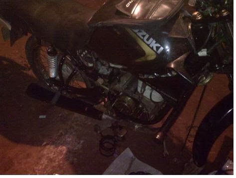
Suzuki Fiero was the first 150cc 4-Stroke bike launched in India. The
Bike was the best 150c bikes of that time. Even when the CBZ powered
with an 156cc, it can produce an output power of only 12.8bhp.
TVS after breaking with suzuki has tried lot to use name of fiero but said to say that they couldn't.
Now a days people talk about APACHE , They don't know Apache engine is just fiero engine modification which belongs to suzuki. :)
Even today it stands as a classic bike in the hearts of Indians.
Specifications:
Engine Displacement: 147.5cc
Engine type: 4 Stroke, SOHC
Output power: 12Bhp@7500rpm
Engine torque: 10.5nm@6500rpm
Fuel Capacity: 13Ltrs
Weight: 115Kgs(dry)/127Kgs(wet)
Transmission: 5 Speed
Top Speed: 110Kmph
My SUZUKI FIERO 2001 MODEL BIKE WAS ABOUT TO CROSS 3 LAC KMS IN SPAN OF 14 YEARS GOT BORED LAST WEEK. I really have experienced a great ride from suzuki fiero bike. Thank you very much to suzuki who has provided such a great model and now i am moving to GIXXER which i believe will give me same taste.
Suzuki Bikes in India
Suzuki has 12 Bikes models available in India. The available
models are Suzuki,Suzuki Gixxer,Suzuki Inazuma, Suzuki Access, Suzuki Bandit,
Suzuki GS, Suzuki Hayabusa, Suzuki Intruder M1800R, Suzuki
Slingshot, Suzuki GSXR, Suzuki Intruder, Suzuki Swish, Suzuki
Hayate, . The minimum priced model of Suzuki is Suzuki Inazuma
priced at Rs 150000 and the maximum priced model of Suzuki is
Suzuki Inazuma priced at Rs 150000. Click Here to find all
Dealers in India
Suzuki Dealers in India
Suzuki Motorcycle India Private Limited is the Indian arm of the
Japanese multinational corporation, Suzuki Motor Corporation
that is headquartered in Minami-ku, Hamamatsu, Japan. Besides
rolling out batches of scintillating bikes and amazing
automobiles, this Japanese company is also involved in the
production of outboard marine engines, wheelchairs, all-terrain
vehicles (ATVs) and small internal combustion engines. Today
standing at the 9th position in the line-up of the largest
automobile manufacturers of the world, Suzuki began its journey
as something completely different - Suzuki Looms Work. Started
by Mr Michio Suzuki in 1909, this company manufactured weaving
looms for the better part of the time till 1951, indulging in
the production of prototype cars for about a couple of years
before the World War II broke out. But, after the cotton market
crashed in 1951, Suzuki abandoned its looms and went back to the
motor vehicles coming up with the first known form of a Suzuki
motorcycle – a motorized bicycle by the name of 'Power Free' in
1952. After building two-stroke engines for more than two
decades, Suzuki moved on to manufacture four-stroke bike engines
in 1976, the first ones being GS400 and GS750. Today, Suzuki
bikes have established their footprints in every part of the
globe, and India is no exception. The Indian markets, these
days, are glittering with the dazzling fleet of new Suzuki bikes
that includes the likes of Hayabusa, GSX, GSX-R1000, GS150R,
Intruder, Bandit, Slingshot and Hayate. Besides these, there is
a whole lot of shining new Suzuki bikes that are waiting for
their launch in India which includes Suzuki B-king, Gladius,
GW250, Inazuma 250, Skydrive and V-Strom. Apart from bikes,
Suzuki India also has a couple of scooters in its portfolio that
are quite popular amongst the Indian crowds – Access and Swish.
Suzuki bikes in India have always been revered for their
stunning looks, futuristic style, unbeatable technology,
extraordinary performance, easy handling and immense
reliability. That's the reason why Suzuki bikes have won so many
awards over the past few years like the Motorcycle of the Year
Award 2010 for Suzuki GS150R and Most Awarded Bike of the Year
Award 2011 for Suzuki Slingshot.


 In every project we have use case documents as a part of requirement gathering.
So once you go through those use case you will have good understanding of the
same.
In every project we have use case documents as a part of requirement gathering.
So once you go through those use case you will have good understanding of the
same.

 that we would use a second flow of events for the case where
the user is not authenticated.
that we would use a second flow of events for the case where
the user is not authenticated.

 The filled
diamond represents the aggregation and the empty diamond represents the
composition. You can see the figure below for more details.
The filled
diamond represents the aggregation and the empty diamond represents the
composition. You can see the figure below for more details.

.jpg)